How to Estimate Floor Space for High-Speed Fillers
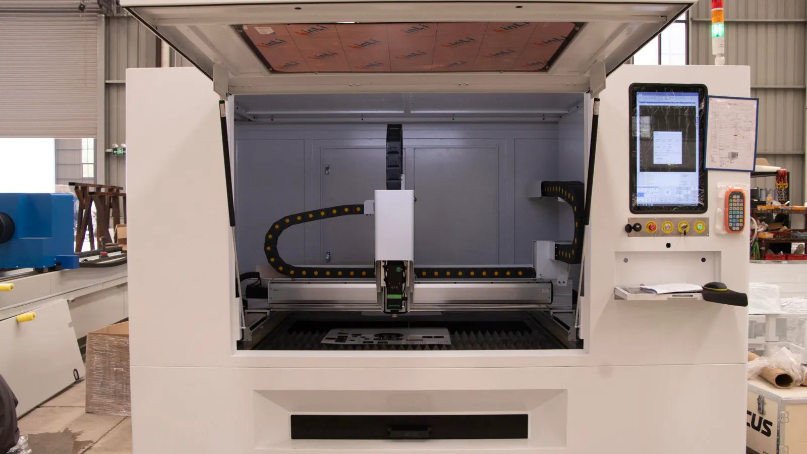
To estimate floor space, measure the machine footprint, add infeed and egress conveyor lengths, and apply safety buffers. Use production volume to determine line speed. This method prevents line bottlenecks and ensures adequate maintenance access for high-speed filling operations.
- Determine the machine footprint from datasheets and add 25 to 50 percent for maintenance clearance.
- Calculate conveyor lengths based on line speed and product changeover requirements.
- Account for infeed staging and egress palletization zones to prevent bottlenecks.
- Verify the final layout by walking the production path with actual product dimensions.
Why Floor Space Estimation Matters for High-Speed Fillers
High-speed fillers demand precise floor space estimation to avoid line bottlenecks and ensure safe operator access. A poorly sized layout causes congestion, limits throughput, and creates hazards during maintenance. Accurate planning requires understanding the relationship between production volume and physical machine dimensions. When the floor space is too tight, operators cannot reach control panels safely, and technicians cannot swap nozzles or clean product contact surfaces without moving the line. This leads to lost production time and increased risk of injury. The machine footprint is just the starting point. The total area required includes infeed and egress conveyors, staging zones, buffer spaces, and safety clearances. Neglecting any of these elements creates a layout that fails under pressure.
Prerequisites for Calculation
Before measuring, gather the following data points. You need the machine datasheet with exact footprint dimensions, including infeed and egress conveyor lengths. Obtain the target production rate in units per hour or per minute. Identify the product type, container size, and any special handling requirements. Know your facility constraints, including door widths and column positions. Review the utility requirements for water, air, and power connections. Note the height of the ceiling and the location of sprinklers or lighting fixtures that may interfere with overhead conveyors. Confirm the weight of the containers and the product, as this affects the structural load on the floor. Check the local safety regulations for minimum aisle widths and emergency exit paths. Without this data, any calculation is a guess.
Step 1: Measure the Machine Footprint
Start with the base footprint of the filling machine itself. This is the area occupied by the machine body, excluding conveyors. Check the manufacturer datasheet for width, length, and height. Add 25 to 50 percent buffer on all sides for maintenance access. This buffer allows technicians to open panels, replace parts, and perform cleaning without moving equipment. The reason for this step is that high-speed fillers require regular cleaning of nozzles, valves, and product contact surfaces. Consider the direction of panel access. If the main service door is on the left side, ensure that side is not blocked by a wall or column. Measure the height of the machine at its highest point, including any overhead fill heads or sensors. This height matters for overhead conveyor routing and for ensuring that operators can see the fill process without climbing. Record the exact dimensions of the machine base, including any protruding guards or safety fencing.
Step 2: Calculate Infeed Conveyor Length
Determine the infeed conveyor length based on line speed and product staging needs. The infeed conveyor must feed product to the filler without starvation. A general rule is one meter of conveyor per 10 percent of line speed above base capacity. The reason for this step is that short infeed sections cause product jams when the filler stops briefly for changeovers or quality checks. If your line speed is 60 units per minute, you need a longer infeed than if running at 20 units per minute. Consider the acceleration and deceleration characteristics of the conveyor belt or chain. A longer conveyor provides a larger buffer for products to settle before entering the filler. Check the angle of the infeed conveyor if it is inclined. A steeper angle may require additional length to prevent product sliding back. Ensure the infeed conveyor has a proper stop or gate to prevent overfilling the filler hopper during changeovers.
Step 3: Calculate Egress Conveyor Length
Measure the egress conveyor from the filler outlet to the next process step. This conveyor must handle full containers at line speed without overflow. A typical egress length is 0.5 to 1 meter per 10 percent of line speed. The reason for this step is that egress congestion pushes back into the filler, causing overfill or product damage. If the next step is a capper or labeler, add extra length for that transition. The egress conveyor must be wide enough to handle the widest container plus any packaging film or tray. Check the drop-off height from the filler to the egress conveyor. Too much height causes impacts that damage containers or spill product. Too little height causes products to slide or bounce. Ensure the egress conveyor has a proper guide rail to keep containers aligned as they move toward the next machine.
Step 4: Apply Capacity Planning Factors
Use production volume to determine required line speed. Convert your target output into units per minute. Match this to the filler’s rated capacity. If your target is 50 percent of rated capacity, you can use a standard layout. If you need 90 percent or more, you must use the maximum conveyor lengths and add buffer zones. The reason for this step is that operating near maximum capacity leaves no room for minor speed fluctuations caused by product variation or ambient conditions. Consider the duty cycle of the filler. Some fillers are rated for continuous operation, while others require periodic downtime for cooling or maintenance. Adjust your capacity plan to reflect this. If you are running multiple shifts, ensure the layout supports the required changeover time between shifts. A tight layout increases changeover time, which can reduce your effective capacity.
Step 5: Account for Infeed Staging Area
Allocate space for the product staging area before the infeed conveyor. This area must hold enough product to keep the infeed running during filler changeovers. A typical staging area is 1 to 2 square meters for high-speed lines. The reason for this step is that staging prevents line stoppages when operators change product formats or refill hoppers. Without adequate staging, every changeover causes a full line stop. Design the staging area with a flat, non-slip surface. Provide a pallet jack or forklift path to move product pallets into position. Consider the weight of the product pallets and ensure the floor can support the load. If you use automated infeed systems, include space for the sensors and guides that detect product presence. The staging area should be large enough to hold one full pallet plus a partial pallet for immediate access.
Step 6: Allocate Egress Buffer Zone
Create an egress buffer zone after the filler outlet. This zone holds finished containers before the next process step. A buffer of 0.5 to 1 square meter is standard. The reason for this step is that buffer zones absorb speed mismatches between the filler and downstream equipment. If the capper runs slower than the filler, the buffer prevents the filler from stopping. Design the buffer zone with a non-slip surface to prevent containers from sliding. Provide a clear path for operators to inspect products in the buffer. If you use automated egress systems, include space for the conveyor rollers and guides. The buffer zone should be large enough to hold a small number of containers without causing a backup into the filler. Check the height of the buffer zone to ensure it does not interfere with overhead structures or lighting.
Step 7: Add Maintenance and Safety Clearance
Add clearance around the entire layout for maintenance and safety. This includes 1 meter on all sides of the machine for emergency stop access. The reason for this step is that operators need quick access to emergency stops and control panels. Maintenance technicians also need space to move carts and tools. Without this clearance, maintenance windows extend significantly. Ensure the clearance is wide enough for a maintenance cart to pass. Check the location of emergency stop buttons and ensure they are within reach of the operator and technicians. Provide adequate lighting in the clearance areas. If the machine has overhead components, ensure the clearance is tall enough for technicians to work safely. Consider the noise levels in the clearance areas. High noise levels may require hearing protection for technicians working in these spaces.
Step 8: Verify with a Physical Walkthrough
Before finalizing the layout, perform a physical walkthrough with actual product. Place boxes or containers representing your product on the floor. Walk the production path from staging through egress. Check for pinch points, restricted access, and congestion. The reason for this step is that two-dimensional drawings miss three-dimensional conflicts. A product that fits on paper may jam in reality due to minor height differences or container tilt. Use the actual product dimensions, including any packaging or trays. Check the clearance between the product and the machine guards. Ensure the product does not interfere with any moving parts. Walk the path in both directions, from staging to egress and from egress to staging. Check the lighting and visibility at each point. Record any issues and adjust the layout accordingly.
Common Mistakes in Floor Space Estimation
The most common error is underestimating conveyor lengths. Many buyers use minimum conveyor lengths from datasheets without accounting for actual line speed. This causes frequent jams and speed reductions. Another mistake is ignoring changeover time. Short staging areas force operators to stop the line during format changes. A third error is placing the filler too close to walls. This blocks maintenance access to nozzles and valves. A fourth mistake is ignoring the height of the machine and overhead structures. This can cause conflicts with sprinklers, lighting, or overhead conveyors. A fifth mistake is not considering the weight of the product and containers. This can lead to floor loading issues and structural damage. Address these mistakes by using the step-by-step method and verifying with a physical walkthrough.
Final Verification Checklist
Use this checklist before approving the layout. Confirm the machine footprint matches your floor dimensions. Verify conveyor lengths meet line speed requirements. Check that staging and buffer zones are adequate for your production volume. Ensure emergency stops are accessible from the operator position. Confirm maintenance clearance is sufficient for all service points. Review the utility connections and ensure they are accessible. Check the floor loading and ensure it can support the machine and product. Verify the lighting and visibility in the layout. Confirm the noise levels are within acceptable limits. Review the safety regulations and ensure the layout complies.
| Component | Minimum Space | Recommended Space | Reason |
|---|---|---|---|
| Machine body | Datasheet dimensions | Datasheet plus 25 percent | Maintenance access |
| Infeed conveyor | 1 meter per 10 percent speed | 1.5 meters per 10 percent speed | Prevent starvation |
| Egress conveyor | 0.5 meters per 10 percent speed | 1 meter per 10 percent speed | Prevent congestion |
| Staging area | 1 square meter | 2 square meters | Changeover support |
| Egress buffer | 0.5 square meter | 1 square meter | Speed mismatch absorption |
| Safety clearance | 1 meter all sides | 1.5 meters all sides | Emergency access |
Capacity Planning in Practice
Capacity planning connects production targets to physical space. If you need 10,000 units per hour, calculate the required line speed. Match that to the filler’s rated capacity. If the filler runs at 150 units per minute, you need about 2.3 hours of run time per day. This determines your conveyor lengths and buffer sizes. The reason for this step is that capacity planning ensures your floor space supports your production goals without overbuilding or underbuilding. Consider the availability of the filler. If the filler is only available for 8 hours per day, you may need a larger layout to accommodate the required throughput. Check the changeover time between products. If you change products frequently, you need a larger staging area and buffer zone to minimize downtime. Review the maintenance schedule. If the filler requires weekly maintenance, ensure the layout supports this without stopping the line.
Troubleshooting Layout Issues
If your line experiences frequent stops, check the floor space first. Look for short infeed conveyors that cause starvation. Check egress congestion that pushes back into the filler. Verify staging areas are too small for changeovers. The reason for this step is that most line stoppages trace back to layout issues, not machine faults. A proper floor space estimation prevents these problems before they occur. Check the alignment of the conveyors. Misalignment can cause jams and damage. Verify the speed settings of the conveyors. Mismatched speeds can cause product pile-up or gaps. Inspect the guards and safety fencing. Ensure they do not interfere with product movement. Check the lighting and visibility. Poor lighting can cause operators to miss defects or hazards. Review the maintenance logs. If maintenance windows are extended, the clearance may be too tight.
Adapting to Flexible Line Speeds
Modern fillers often run at varying speeds depending on product type. Your floor space must accommodate both minimum and maximum speeds. Design for maximum speed but ensure the layout works at minimum speed. The reason for this step is that flexible lines change product formats frequently. A layout that works at high speed may cause congestion at low speed due to conveyor speed mismatches. Check the speed range of the filler and the conveyors. Ensure the conveyors can run at the minimum speed without slipping or stalling. Verify the buffer zones are large enough to absorb speed changes. If you use automated infeed and egress systems, ensure they can adjust speed to match the filler. Test the layout at both minimum and maximum speeds. Record any issues and adjust the layout accordingly.
Conclusion of Method
The floor space estimation method combines machine dimensions, conveyor calculations, and safety buffers. Start with the machine footprint, add conveyors based on line speed, and apply capacity planning factors. Verify with a physical walkthrough. This approach prevents bottlenecks and ensures safe, maintainable operations. Use the verification checklist to confirm all requirements are met before installation.
Frequently asked questions
How do I know if my infeed conveyor is too short?
If the filler frequently stops due to product starvation, the infeed conveyor is likely too short. Add more length or increase staging area size.
What if my product changes frequently?
Increase your staging area to 2 square meters or more. This allows operators to change formats without stopping the line.
How much clearance do I need around the machine?
Allow 1 to 1.5 meters on all sides. This ensures emergency stop access and maintenance clearance for nozzles and valves.
Can I use the same layout for different line speeds?
No. Design for your maximum expected line speed. Shorter conveyors cause congestion at high speeds and starvation at low speeds.
What should I do if my floor has columns or doors?
Adjust the layout to work around obstructions. Keep emergency stops accessible and maintain safety clearance. You may need to shorten conveyors or add buffer zones.